Google Analytics

Sunday, September 17, 2023

LED VU Meter

This post will be a bit different from my typical posts.  I'm basically just writing documentation on a project that's just been completed.  

This is the prototype device in a classroom. It was intentionally designed to show the components. 

And this is the second revision, miniaturized and cleaned up quite a bit.


Each device has an Arduino Pro Mini, Max 9814 Microphone, a momentary push button, and 50 NeoPixel LEDs.


The device schematic


What is a volume unit (VU) meter?


A VU meter is a device that visually displays the strength of an audio signal.  In this case, the LEDs light up and change colors based on how loud sounds in the environment are. 


How does it get used?


The light emitting diode (LED) strip should be attached with an adhesive on to a vertical surface.  The microcontroller enclosure or “brain box” should be affixed similarly at the bottom of the LED strip. When the USB cable is plugged in, the device should start to operate.  On the bottom left part of the enclosure there is a momentary push button that can pause the operation of the device and turn off the LED strip. 


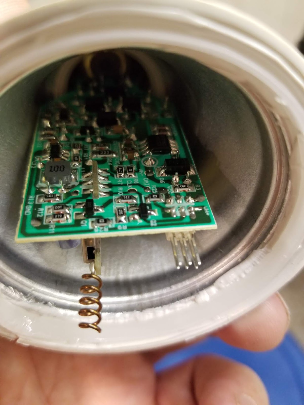
The lid can be removed so that the components and wiring are visible in case the user would like to see how it’s wired and better understand how it works. 


The device requires standard 5 Volt USB power from a USB power supply.  It draws a maximum of 1 amp so even low-end USB power supplies should be plenty to operate the device. 


What are the troubleshooting steps?


If the LEDs do not light up when the device is plugged into a USB port, leave the device unplugged for 5 seconds and plug it in again and/or try a different USB power supply. 


How does it work?


Let’s start with the hardware.  

The microcontroller board contains an 8-bit ATMega328 running at 16Mhz, or 16 million cycles per second.  It is connected to a component board that contains a microphone with a built-in amplifier and automatic gain control operated by a MAX9814 integrated circuit (IC). The microcontroller also drives a WS2812B LED (commonly called “Neopixels”) strip.  Lastly, there is a momentary push button connected to the microcontroller to allow for user input. 


On to the software.  

The microcontroller allows a single program to be stored and it will run that program whenever it has power. By its nature, the microcontroller runs this single program in an infinite loop.  

The program is written in C using the Arduino development environment. Upon booting, the software initializes the microphone and LED strip.


The heart of the program is an algorithm called a fast Fourier transform (FFT).  A FFT quickly computes the discrete Fourier transform (DFT) of a signal. In essence, the algorithm converts the analog audio data from the microphone into the signal’s individual spectral components which produces the signal’s frequency information. It then computes those frequencies to find the delta between the baseline and the peaks of the input signal. The practical upshot of this is that you end up with a number that represents the loudest sound picked up by the microphone at a given moment.. This input and processing cycle happens approximately 15 times per second. 


The program then takes the data from the FFT and uses it to compute the signal data that will be sent to the LED strip. It does this by using the numeric result of the FFT to determine how many LEDs need to be lit up and then looks up data in a rainbow color wheel table to determine the order of colors that should be displayed leading up to the last/top LED.   With this information, it sends a digital signal to the LED strip telling it to light up from 0 to the Nth LED, and to fill the intervening LEDs the colors prescribed in the color wheel table. As a bit of flair, the microcontroller will also display a “falling peak” that will appear to drop down from the maximum level of the current cycle to the maximum position of the next cycle, lighting one LED at a time.


The “pause” functionality is pretty straightforward.  If the microcontroller detects a push and release of the button within 200ms, the FFT processing will be suspended and the LED strip will set each element to be off until another button press is registered or the device is otherwise restarted.  


It may be important to note that while this device measures volume from the environment, no audio data is stored and the device has no ability to connect to any data network such as WiFi. 


Where did the case come from?


The case was designed in computer-aided design (CAD) software called Fusion360.  The design of the lid of the case went through about 4 iterations while the base part that holds the electronics went through about 14. The design attempted to balance aesthetics with functionality. The case’s outside edges are all filleted, including the edges of the circular extrusions for the button and wiring. The lid provides vents for airflow and full access for the microphone to pick up sounds from the environment.  The base provides stand-offs for the components and space for the wiring. The components are attached inside the case with thermoplastic adhesive and the lid attaches to the base via a self-centering friction-fit mechanism. 


All of the enclosure iterations were printed on a fused deposition modeling (FDM) 3d printer using polyethylene terephthalate (PET) filament.  PET is what most American beverage containers (such as 2 liter soda bottles) are made from and is 100% recyclable.  


Why make this?


The primary goal of this project was to build a tool that could be helpful in classroom management. It’s also important to show young people that STEM areas can be neat and exciting. This tool provides a way to start a conversation about electronics and technology, mathematics, programming, CAD, and other engineering-related skills.  


Who built this?


My name is Don Howdeshell. I’m a software engineer/systems administrator at Missouri S&T and I’m always looking for challenging projects that also have a practical use.  


This project was started from a conversation with a 6th grade teacher looking for a way to allow students to self-monitor the volume level of their voices while working on projects within the classroom.  


The prototype device has operated for the better part of a year and has been helpful both as a volume monitoring device and as a conversation starter with students who have a curious mind, are interested in STEM fields, and/or just think it’s interesting.  


Monday, September 7, 2020

Minecraft Cube Light

 Thingiverse has a lot of neat stuff.  My son found a Minecraft Diamond Ore Lamp and decided that he wanted one.  I see that the creator has some links to tutorials and whatnot, but I saw them after the fact and did things a bit differently.  


Ultimately, I threw WLED onto an ESP8266, added 5 Neopixels, some Vellum as a diffuser, and called it good.  The neat part of this was being able to add a single IFTTT command to be able to change the colors via Google Assistant/Home.  

All of my home automation stuff through Google Home goes through an external service such as IFTTT, then to a secure bridge that I've designed on the backend.  The command goes from Google to IFTTT to my server to the IoT device.  I was able use IFTTT's "phrase with a single text ingredient" to call multiple different states of the LED block.  


Here are some examples of diamond, emerald, redstone, gold, lapis, and iron.   


Here are some images of the build process. First, there is the printed cube with vellum glued to the inside.  


The system is run by a NodeMCU ESP8200 board. 


Here's a video of the system in action with the cycles sped up to show the colors.


Thursday, December 19, 2019

Hacking a cheap RGB LED light bulb in order to keep foreign, closed source firmware off of the network

Gotta love Black Friday sales.  This year I picked up a pair of Merkury RGB LED light bulbs for $15 to see what I could do with them. I assumed that it would be using an ESP8266 and thankfully I was ultimately right, but let's not get ahead of ourselves...


When I opened the box and started searching online for information on these bulbs, I wasn't able to find much information and certainly not any write-up about it.  Hopefully this helps the next guy.

The bulbs are branded Merkury, but ultimately they seem to be manufactured by Tuya as most smart bulbs are.  Immediately I was able to find the absolutely amazing Tuya-Convert project.  Using Tuya-Convert is entirely automated so understanding the nuts and bolts is not strictly necessary. To summarize the project: it uses a Linux system with WiFi (like a Raspberry Pi) to start a special Access Point SSID along with a web server, DHCP server, and DNS server so that the ESP8266 auto-connects to that AP and all DNS queries and URLs are redirected to the server so it can ultimately lie about a firmware update being available. Once the server lies to the ESP, the ESP attempts to download the firmware update which is our own custom firmware image (Tasmota & ESPurina are included, but any firmware will work.)  Once the ESP flashes the firmware it is then able to be reconfigured or reflashed at will. Tuya-Convert is an incredible project and can help you flash firmware completely over the air (OTA.) Do not bother with the Geeni app in the Play Store or App Store.

As amazing as Tuya-Convert is, bad things can still happen. I was able to flash one bulb and get it working 100% without opening it up. However, when I was experimenting with the second one, I got a bad flash or bad config. Which meant I needed to open it up.

Let's start with the LEDs themselves:


As you can see above, there is a ring of the "white" LEDs and 6 of the RGB LEDs sitting toward the center.  All of the LEDs are dimmable. This layout is an interesting design choice and it helps explain why this bulb has a rated brightness of 1080 lumens when most other bulbs are currently closer to 800 lumens.

So what's inside?!  After using a small cutting tool or razor blade to cut the adhesive around the diffuser globe, we can remove it.


With the diffuser removed, we can now see all of the LEDs, the LED driver IC (more on this later), the ESP8266 antenna, some test pads, and the pin connector.


Once the diffuser is removed, use the cutting tool to cut the white silastic-type adhesive. The aluminum plate that the LEDs are attached to will need to be gently pried out once the silastic has been cut.

Inside we find a double-sided PCB with some through-hole components as well as a lot of SMD components.

At this point we can see that the PCB is double-sided.  The "top" has several capacitors and an inductance coil so we can probably assume that it handles some of the AC to DC conversion and power supply aspects while the components on the "bottom" likely include the switch mode power supply regulator and, to quote Mehdi, the FULL BRIDGE RECTIFIER!! among other components. 

It turns out that you can remove the cap from the tip of the base to detach one of the AC lines and the second can be popped off of the internal aluminum cup that holds the board. This will allow you to completely remove the PCB. I was able to just pop the tip back together for the hot wire, but I had to solder the neutral back to the side of the aluminum cup/case.  I believe it may have been spot-welded at the factory. 

Once removed you can get a good look of the "bottom" of the PCB.  Unfortunately I didn't think to take a good photo of it, but you can see that this board produces 3.3V for the ESP8266 as well as 12V for driving the LEDs. 


With the board removed, we can easily get to the RX, TX, Ground, 3v3, and GPIO 0 pads so we can flash it over serial. 

If you are better at reading than I was at around midnight when I was working on this, you'll notice that label where the blue wire is connected reads "IO0" and is actually GPIO 0, which is required to be pulled to ground in order to enter flash mode. Apparently I misread what was under that black scorch mark near the gray wire and couldn't figure out why the hell the ESP wasn't recognized by my computer. <facepalm>  So we can see the RX, TX, and GPIO 0 wires connected here while 3v3 and ground are connected on the back. I hooked this up to my 3.3V capable FTDI serial board and flashed the latest version of Tasmota.

Now, on to the board configuration once it's flashed.  Tasmota won't do a whole lot of good unless you have it configured correctly.  This is the step that was the most difficult because of the lack of information online.  I looked up what I could about the LED driver IC that was on the LED board with virtually no luck. The part number is either SM726EB or SM276EC, depending on the version of the board.  After a lot of trial and error, I finally figured out that this chip operates the same way as the SM16716 in that it needs a data and clock signal in order to function.  If you are using Tasmota and are looking for the proper settings for this device, look no further.  The following template should work:

{"NAME":"Merkury Smart Bulb","GPIO":[0,0,0,0,37,38,0,0,141,142,140,0,0],"FLAG":0,"BASE":18}

Alternatively, you can configure it manually with the following:

Device: 18 (Generic)
GPIO4: PWM1 (white/yellow LED temperature)
GPIO5: PWM2 (white/yellow LED brightness)
GPIO12: SM16716 DAT (RGB LED Driver Data; Color and Brightness)
GPIO13: SM16716 PWR (RGB LED Driver Power)
GPIO14: SM16716 CLK (RGB LED Driver Clock)


Once Tasmota is configured, it should have sliders for the different LEDs and the API can be configured to integrate into the desired home automation system.  Now we can enjoy our smart bulb without certain governments snooping on our every move and who-knows-what-else via the apps that would otherwise need to be on our phones.  Happy hacking!


As always, if anyone has questions or sees a mistake, please don't hesitate to comment.  


Monday, September 30, 2019

Adding Qi wireless charging to SoundPeats Bluetooth wireless headphones

Hi!  It's been quite a while since I last posted.  Please accept my apologies; I'm looking forward to sharing several new projects with everyone over the next couple of months.

So let's get on with it.

I recently purchased a set of wireless headphones from Amazon and they have turned out to be surprisingly good.  Except one thing.  How can a set of headphones call itself "wireless" when you have to plug them in?!

The headphones in question are SoundPEATS TrueFree +.  I have no connection with Amazon or this... SoundPEATS (?) company outside of being a customer.  And, so far, a reasonably happy customer at that.  I've also previously purchased a Qi wireless charging kit for my old Galaxy S5 that has come and gone, but I saved the charging coil "just in case."  Well, today ended up being that day.

First, I used some guitar picks to open the travel/charging case of the headphones. I've not been able to find any photos of a teardown, so if someone is looking for a teardown or disassembly of SoundPEATS TrueFree + then I hope Google brings you here.

The teardown showing the 800mAh battery:


I've seen this battery reported as 800mAh and it appears that is accurate.

With the case open, we can start eyeing our Qi coil to make sure it's going to fit reasonably well. Here is the coil that I had on hand.
The 600mAh Qi charging coil

It fits!!


So the way the charging coil fit in the Galaxy S5 is that the 3 pins (actually, they are small cubes) make contact with the 3 springs inside of the battery cover.


[Right] I had to remove the +5V and ground terminals from the charging coil in order to get a clean solder connection.


The board is single sided.  


The next task was to examine the board and find out if there were any pads that were on the VCC and ground traces.  Using my multimeter, I was able to find a ground pad next to the large IC and a VCC pad close to the MicroUSB port.  These pads are circled below.

 The board is fairly well laid out and it provides 5V DC to each of the ear plugs which will have their own battery management system.


 After attaching everything, it's time to test.
It works!! The charger indicator is blue and the charging LEDs on the board are illuminated.

Now it's time to get everything put back together.  

I made sure to put some hot glue under the pogo pins to ensure that they stand proud on the other side and connect to the ear buds properly. 

Carefulling...

Bend it over... Still carefulling...


 Once it's in the case, I snapped everything back into place.  It worked out well with only a couple of apprentice marks.


 Now my wireless headphones are truly wireless!

As always, I'm happy to answer any questions.  Thanks for checking it out.


Sunday, December 31, 2017

An updated version of my Clock for Kids

Now that my daughter is 5 and is able to tell time, I wanted to make a new clock for my 3 year old son. Since my first prototype was green, I passed it down to my son and built a new pink clock for my daughter.  Just like v1, v2 does not change any of the functionality of the clock itself, it only adds an RGB LED.

Here is the link to my first version. It was powered by a Raspberry Pi Model B (not B+).  Now that the Pi Zero W is out and it fits perfectly inside of these clocks, I decided to use it for v2.  The clock is the same Walmart alarm clock as the first one.  Here are some of the photos from the build process:

Obligatory finished product image first.


The BOM is a clock, a Pi Zero W, MicroSD card, and a Shiftbrite.  
A Neopixel could be used instead but the Shiftbrite is far brighter.


The opening of the "light cone" needed to be enlarged to fit the new LED.  My Dremel to the rescue!


The wiring for the Shiftbrite and the 3.3v to power the clock's internals.


I used the 3.3V line of the Pi to power the clock. The Shiftbrite works on 5V, so I had to run a lot of different wires for everything.


The Pi Zero W fits in the clock perfectly.

A notch cut out of the back to power everything.


The final fitting.


Again, I used pretty much the exact same software from my GitHub repo. The only real difference between v1 and v2 is in the hardware. Instead of a 3.3V power supply crammed into the system, I used the voltage regulator on the Pi itself so it only needs power input and does not require external wires like v1.

I'll update this post with photos of the clock operating.  Also, I'll be posting soon on how to integrate everything with Google Home. It's very nice to be able to tell Google Assistant to tell the kids it's time for bed.


I'm happy to answer any questions that you might have.  If this has helped or inspired anyone, any donations will be very appreciated and will result in more cool stuff being built and posted here. Thanks for checking out my project!