After using my DIY Ambilight for a few days I got tired of plugging in and unplugging the power supply to the ShiftBrite shield, so I finally broke down and added a switch to turn it on and off. Now that I've been using it for a few weeks, I'm tired of having to turn it on and off manually every time I want to watch TV.
I noticed that my Samsung TV had a serial interface in the form of the EX-Link connector to see if I could electrically tell if the TV was on or not. No luck. I tested the USB ports next and found that when the display is off, the USB interfaces have about .15V and just over 5V when the display is on. Bingo. Now to get a relay.
This relay requires 3.5V to activate and less than .25V to deactivate.
My next step was to add a relay to my ShiftBrite shield and cut an extra USB extension cable and wire the +5V wire (red) and the ground (black) wire to the coil of a relay. My DIY ShiftBrite shield is now wired as the above illustration indicates with the USB +5V & Ground lines coming from the TV. Since the coil in the relay will cause a brief voltage spike that could damage your TV's USB port, it is important to make sure that the protection diode is added. Just add it 'backwards' across your relay coil so the energy stays in the coil and doesn't go back into the USB port.
Here is what my finished ShiftBrite shield looks like (the protection diode is on the bottom out of view):
Since most LCD TVs now have USB ports, I figured that this build could end up helping someone else. I certainly hope so!
We try to hold Field Day at least twice a year for our Desktop Engineering students. This year Field Day was on 10/07/11. We decided to try to shoot a propane tank this time. Here is what happens when you shoot a 1 LB propane tank with an AR15 (.223) from about 35 yards. I was standing about 15 yards off to the side filming this. I'm glad Bryan is such a good shot.
This is my DIY Ambilight for my home theater PC. In this tutorial I plan to give detailed instructions on how to build a multichannel Arduino-based Ambilight for about $40 plus the Arduino which can be reused for other projects. The bill of materials include 6+ ShiftBrites (your call, I wouldn't do less than 6 though), a printed circuit board, wire, and headers. Additionally this will require all of the components needed to get over 0.5 Amps at 5.5-9V DC on to the board to drive the ShiftBrites; this cannot be reasonably done over USB power. My ultimate goal here is to give others some ideas on how to go about this project for less money than it would cost to essentially buy everything in a kit. I went in to this trying to be resourceful and I feel pretty good about how it turned out. If this guide has been helpful, please consider donating.
The first challenge was to construct my own ShiftBrite Shield. They can be purchased from Macetech's store, but I wasn't interested in spending that much money on one when I could build what I needed for a fraction of that cost. As you can see, my ShiftBrite Shield is a bit more complex than Macetech's because I didn't have a transformer that could push enough amperage at those voltages. My solution was to use a 12V 2A transformer and step the voltage down using an LM317T voltage regulator. Here is a rough design of my board. The resistors represent the total resistance of the line (ie. 2 x 470Ω in parallel = 235Ω and 1.2kΩ + 100Ω = 1.3kΩ). I've since added a power switch, but that should be simple enough to figure out. If you have a 7V 1A transformer then the voltage regulator stuff can be skipped. It is probably a really good idea to have at least a 1000µF capacitor (if not the 100µF as well) to help eliminate some line noise.
It may be important to point out here that the ground from the ShiftBrite Shield is connected to the ground of the Arduino. This is necessary for the clock to work. Also, make sure you don't send any voltage down an Arduino port or you could damage your device.
Additionally, unless you want to write your own code to handle sending packets to the ShiftBrites, the pins of the Arduino need to be mapped to these PWM pins on the ShiftBrite. The Arduinoatmo Google Code site has some nice and efficient code to bitshift and use SPI to determine when to continue without using the dreaded delay function. More on the code later - just make sure you know what you are doing if you use different pins.
As you can see above, you will likely need a decent heatsink for the LM317T to dissipate any heat. This fairly large heatsink gets pretty hot to the touch after a few hours of operation.
Since I'm opting to use the materials that I have on hand to do this, I decided against buying cables as I have a ton of Cat5 laying around. I needed 6 pins, so I cut off the blue wires and made sure to wire everything up the same way on both ends. Once I finished wiring the ShiftBrites, I went back and applied hot glue to act as an insulator between the wires. When wiring your ShiftBrites, take note that the Data/Latch/Enable/Clock pins are labeled I and O (as in Input and Output) and not 1 and 0. Embarrassingly I did not pick up on that right away and was wondering why it would not work when I sent a signal over the D0 pins but did on the D1 pins.
As you can see, I'm using ShiftBrite 1.0 because while I was building this version 2.0 came out. One of the main changes to the design was to add a power filtering capacitor to the device. As awesome as these devices are, they definitely need the capacitor. Granted this 2200µF capacitor is overkill, it is what I had on hand. I started with 2 of these capacitors on my chain, but because of noise issues that I was having, I went back and put a 220µF capacitor on every other ShiftBrite 1.0 in my chain.
On to the software. For my setup, I'm using boblight on Fedora to capture from X11 because Mythtv does not have this functionality built in. VLC and AtmoWin work very well on Windows if you are going that route. Either way we get the same packet information to the Arduino over the serial interface. Fun3 has some good technical info on the Atmolight protocol. Basically we get 4 bytes and then 14 bytes of actual data per packet. The packet and protocol information is good to understand, but largely inconsequential if you are using the Arduino sketch from the Arduinoatmo project because it will handle things for you.
The next step is to upload the software to the Arduino. It's probably a good idea to start with some sketches that don't require any input from the computer. This will allow you to test your hardware setup on its own. Both of these sketches require you to change the pinout to what we are using.
The former is Macetech's code, the latter is Ashley Hughes' code - both modified to use the pinout described for the DIY ShiftBrite Shield. Whichever way you go, you should be able to get the ShiftBrites to do something at this point.
For this to work with your videos, you need to get boblight compiled or installed on your HTPC. I could not find an RPM for Fedora (although I'm sure they exist), but compiling it from source was pretty simple. Just follow the instructions on the project wiki. It wasn't any harder than installing the dependencies listed with yum (replace 'apt-get' with 'yum' on Fedora), running the ./configure script and then running make.
Once that is set up, we need to configure boblight. Below is my boblightd.conf file:
[global] timeout 20 interface 127.0.0.1 port 19333 interpolation on proportional 100.0 saturation 3.0 value 10.0 valuerange 0.0 1.0 use yes method average threshold 20
[device] name ambilight type atmo output "/dev/ttyACM0" rate 38400 channels 15
interval 200 prefix FF
[color] name red rgb FF0000 gamma 1.0 adjust 1.0 blacklevel 0.0
[color] name green rgb 00FF00 gamma 1.0 adjust 1.0 blacklevel 0.0
[color] name blue rgb 0000FF gamma 1.0 adjust 1.0 blacklevel 0.0
[light] name center color red ambilight 1 color green ambilight 2 color blue ambilight 3 hscan 25 75 vscan 25 75
[light] name left color red ambilight 4 color green ambilight 5 color blue ambilight 6 hscan 0 10 vscan 0 100
[light] name right color red ambilight 7 color green ambilight 8 color blue ambilight 9 hscan 90 100 vscan 0 100
[light] name top color red ambilight 10 color green ambilight 11 color blue ambilight 12 hscan 0 100 vscan 0 15
[light] name bottom color red ambilight 13 color green ambilight 14 color blue ambilight 15 hscan 0 100 vscan 85 100
This goes in the file: /etc/boblightd.conf. When boblightd gets executed, it will run in the background listening for something to tell it what to do. To break it down, boblightd talks to the serial interface on the Arduino over USB and listens for data from another program. In this case I'm using boblight-X11 - a program that will run on the current X11 session and grab images from X11, process them, and send the information to boblightd which will in turn process it into the proper protocol (atmo) and then send the data to the specified device. If you want to learn more about the protocol that you are using, it is easy enough to send the output of the boblight daemon to a text file so you can look at the data being sent; just replace /dev/ttyACM0 in my config file to the location of a file on the hard disk. So how can we find out what to put in the device field so boblight can talk to the Arduino? Start by running 'tail -f /var/log/messages' from a shell. You will likely see some things scroll by as DHCP leases get renewed and whatnot. When you plug in your Arduino to a USB port, it should read something like this:
kernel: [453420.004354] usb 3-2: USB disconnect, address 7 kernel: [453422.904031] usb 3-2: new full speed USB device using ohci_hcd and address 8 kernel: [453423.052623] usb 3-2: New USB device found, idVendor=2341, idProduct=0001 kernel: [453423.052629] usb 3-2: New USB device strings: Mfr=1, Product=2, SerialNumber=220 kernel: [453423.052633] usb 3-2: Product: Arduino Uno kernel: [453423.052635] usb 3-2: Manufacturer: Arduino (www.arduino.cc) kernel: [453423.052638] usb 3-2: SerialNumber: 6493534363335130B041 kernel: [453423.054731] cdc_acm 3-2:1.0: ttyACM0: USB ACM device
Typically it will be something like ttyS0, ttyUSB0, or in my case, ttyACM0. Simply put the device path into the boblight config file. Once boblightd is running, the Rx light on the Arduino should be flashing pretty rapidly or on constantly.
By default boblightd does not fork, so if you want to run it from a startup script you need to call it with the -f parameter or it will die when the startup script is done. Also by default boblight-X11 only samples the screen once every .5 seconds. I call 'boblight-X11 -t 0.1' so it samples it 10 times a second. The behavior of this is up to you. Be sure to use top to see how much CPU usage these two programs are using. 'top -d 1' will give you one second updates. It should be using no more than 5% CPU on a reasonably new machine. Mounting the ShiftBrites to your television/display is going to likely be the last challenge in this project. After bouncing some ideas off of my friends, I decided to go with plexiglass mounted to the back of the TV by the wall mount holes. On my Samsung the screws were 6 mm with 1.00 threads. I used 40 mm long screws with full threads to make sure the plexiglass was far enough from the back of the display so it could vent. I used 2 washers and a nut all tightened to the head to hold the plexiglass in place and another nut that would be tightened against the TV itself to hold the whole setup securely.
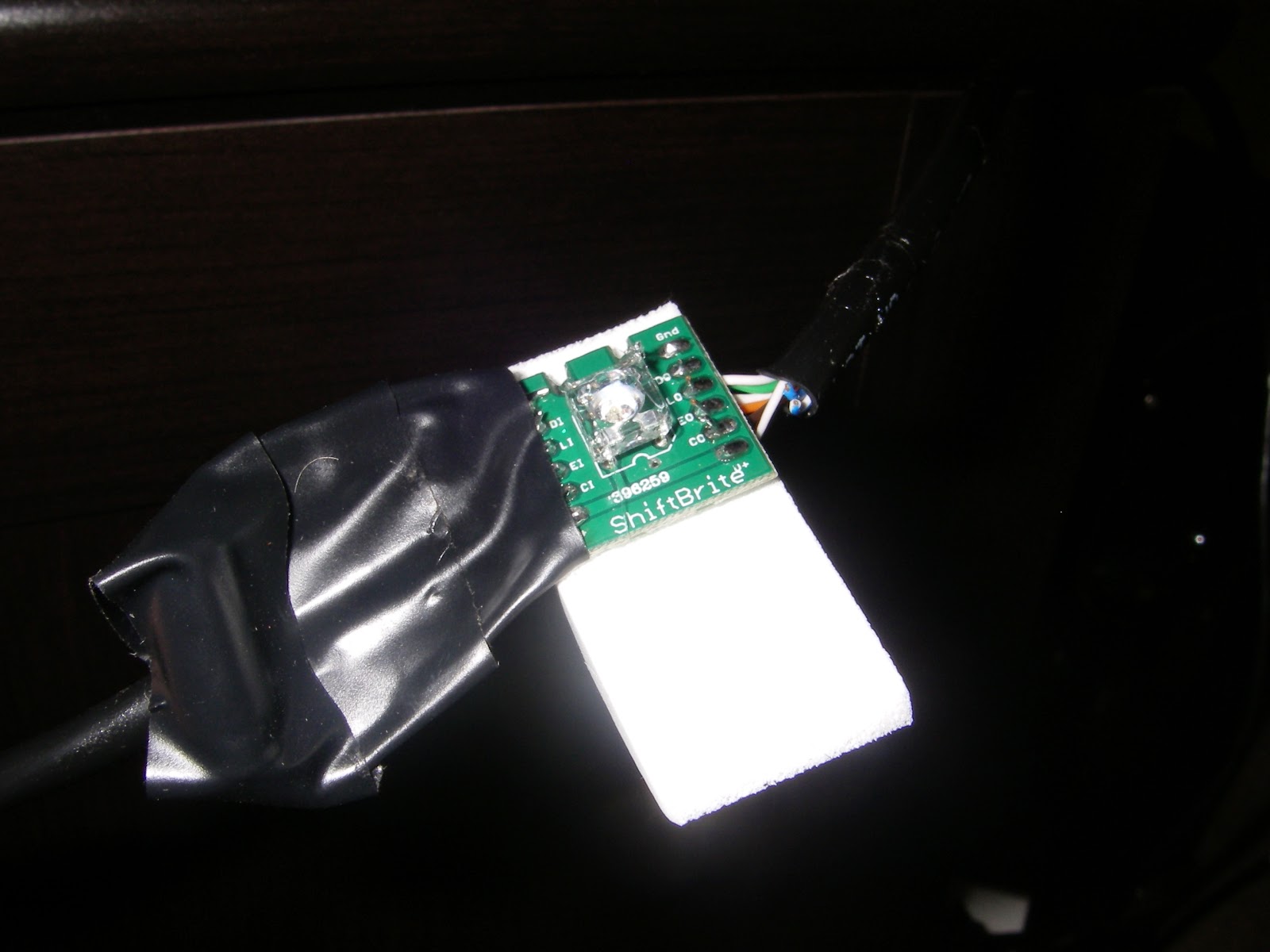
My power cable had enough room in the spacing to be manipulated, but the input cables did not. Since I wanted a ShiftBrite at the bottom corner, I had to cut out a space for the input cables but leave a place for the LED. We won't talk about the horrible job I did cutting it, but it works.
I needed to find a way to aim the ShiftBrites once I mounted them. I didn't want to have them aimed directly back on to the wall, so again I looked for an unorthodox solution and found one in my wife's wedge-shaped makeup applicator sponges. Hot glue seemed to be a good adhesive choice since it is strong and I know I can get it off of the ShiftBrites without damaging the subcomponents. The mass of tape on the left is that 220µF capacitor mentioned earlier.
Here is what the back of my TV looks like with the plexiglass and all of the ShiftBrites mounted. As you can see, some of the LEDs (like the top center) need to be aimed a bit better. But this is the gist of my mounting solution. The last thing that I needed to do is to find a good diffuser to put over the ShiftBrites. Because of the proximity of my television to the wall I get some odd colors on the wall. For example when a ShiftBrite is shining white, I can see the green subLED pretty strongly. My solution to this was to cut up the flat sides of a plastic water jug in 2.5" squares. I stapled two together on the edge of one side and attached them to the pieces of foam. This acts as a good enough diffuser until I am able to find something better. Here is a sample video of what my DIY Arduino Ambilight looks like.
Here are a couple of other example of what it looks like after I added the diffusers. There's not much color on the first one, but it illustrates some of the difficulty that the ShiftBrites have with displaying pure white without seeing the individual subLEDs. If you look really closely you can see some green tints in the video when there is only supposed to be white. Those tints were really well defined and annoying before the diffusers and are almost unnoticeable in person after the diffusers.
I'd love to hear any ideas that anyone else has on this or a similar project! Please leave any comments below. If this has been helpful, please consider donating.
Quick $10
Disclaimer: I've tried to reduce errors, exaggerations, and outright lies in this tutorial. If I missed something, something is wrong, or you have questions then please post below and I'll update the info in the post. If you build one of these devices and it burns your house down then I cannot be held liable, yet I offer my condolences. If you attempt to hold me responsible then I *will* laugh at you. This information is provided as-is with no warranty.


