When I opened the box and started searching online for information on these bulbs, I wasn't able to find much information and certainly not any write-up about it. Hopefully this helps the next guy.
The bulbs are branded Merkury, but ultimately they seem to be manufactured by Tuya as most smart bulbs are. Immediately I was able to find the absolutely amazing Tuya-Convert project. Using Tuya-Convert is entirely automated so understanding the nuts and bolts is not strictly necessary. To summarize the project: it uses a Linux system with WiFi (like a Raspberry Pi) to start a special Access Point SSID along with a web server, DHCP server, and DNS server so that the ESP8266 auto-connects to that AP and all DNS queries and URLs are redirected to the server so it can ultimately lie about a firmware update being available. Once the server lies to the ESP, the ESP attempts to download the firmware update which is our own custom firmware image (Tasmota & ESPurina are included, but any firmware will work.) Once the ESP flashes the firmware it is then able to be reconfigured or reflashed at will. Tuya-Convert is an incredible project and can help you flash firmware completely over the air (OTA.) Do not bother with the Geeni app in the Play Store or App Store.
As amazing as Tuya-Convert is, bad things can still happen. I was able to flash one bulb and get it working 100% without opening it up. However, when I was experimenting with the second one, I got a bad flash or bad config. Which meant I needed to open it up.
Let's start with the LEDs themselves:


As you can see above, there is a ring of the "white" LEDs and 6 of the RGB LEDs sitting toward the center. All of the LEDs are dimmable. This layout is an interesting design choice and it helps explain why this bulb has a rated brightness of 1080 lumens when most other bulbs are currently closer to 800 lumens.
So what's inside?! After using a small cutting tool or razor blade to cut the adhesive around the diffuser globe, we can remove it.

With the diffuser removed, we can now see all of the LEDs, the LED driver IC (more on this later), the ESP8266 antenna, some test pads, and the pin connector.
Once the diffuser is removed, use the cutting tool to cut the white silastic-type adhesive. The aluminum plate that the LEDs are attached to will need to be gently pried out once the silastic has been cut.

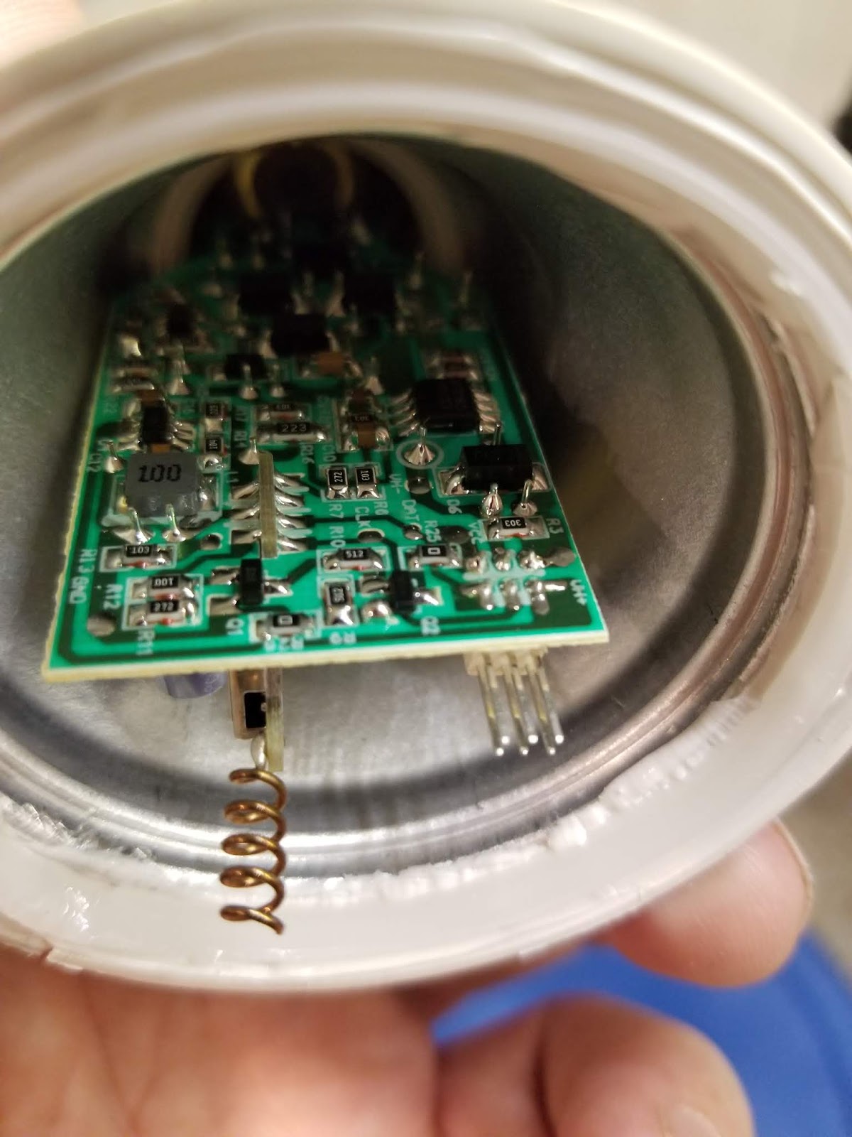
Inside we find a double-sided PCB with some through-hole components as well as a lot of SMD components.
At this point we can see that the PCB is double-sided. The "top" has several capacitors and an inductance coil so we can probably assume that it handles some of the AC to DC conversion and power supply aspects while the components on the "bottom" likely include the switch mode power supply regulator and, to quote Mehdi, the FULL BRIDGE RECTIFIER!! among other components.
It turns out that you can remove the cap from the tip of the base to detach one of the AC lines and the second can be popped off of the internal aluminum cup that holds the board. This will allow you to completely remove the PCB. I was able to just pop the tip back together for the hot wire, but I had to solder the neutral back to the side of the aluminum cup/case. I believe it may have been spot-welded at the factory.
Once removed you can get a good look of the "bottom" of the PCB. Unfortunately I didn't think to take a good photo of it, but you can see that this board produces 3.3V for the ESP8266 as well as 12V for driving the LEDs.

With the board removed, we can easily get to the RX, TX, Ground, 3v3, and GPIO 0 pads so we can flash it over serial.
If you are better at reading than I was at around midnight when I was working on this, you'll notice that label where the blue wire is connected reads "IO0" and is actually GPIO 0, which is required to be pulled to ground in order to enter flash mode. Apparently I misread what was under that black scorch mark near the gray wire and couldn't figure out why the hell the ESP wasn't recognized by my computer. <facepalm> So we can see the RX, TX, and GPIO 0 wires connected here while 3v3 and ground are connected on the back. I hooked this up to my 3.3V capable FTDI serial board and flashed the latest version of Tasmota.
Now, on to the board configuration once it's flashed. Tasmota won't do a whole lot of good unless you have it configured correctly. This is the step that was the most difficult because of the lack of information online. I looked up what I could about the LED driver IC that was on the LED board with virtually no luck. The part number is either SM726EB or SM276EC, depending on the version of the board. After a lot of trial and error, I finally figured out that this chip operates the same way as the SM16716 in that it needs a data and clock signal in order to function. If you are using Tasmota and are looking for the proper settings for this device, look no further. The following template should work:
{"NAME":"Merkury Smart Bulb","GPIO":[0,0,0,0,37,38,0,0,141,142,140,0,0],"FLAG":0,"BASE":18}
Alternatively, you can configure it manually with the following:
Device: 18 (Generic)
GPIO4: PWM1 (white/yellow LED temperature)
GPIO5: PWM2 (white/yellow LED brightness)
GPIO12: SM16716 DAT (RGB LED Driver Data; Color and Brightness)
GPIO13: SM16716 PWR (RGB LED Driver Power)
GPIO14: SM16716 CLK (RGB LED Driver Clock)


Once Tasmota is configured, it should have sliders for the different LEDs and the API can be configured to integrate into the desired home automation system. Now we can enjoy our smart bulb without certain governments snooping on our every move and who-knows-what-else via the apps that would otherwise need to be on our phones. Happy hacking!
As always, if anyone has questions or sees a mistake, please don't hesitate to comment.